Why CNC Machined Aluminum Parts Look Different Across Batches — Case Study
A real CNC machining case showing how BERGEK built a fully repeatable process for consistent anodized aluminum parts.
Introduction: The Real Challenge in CNC Machining Is Consistency
For many engineering teams sourcing CNC machining parts, precision turning parts, or anodized aluminum components, dimensional accuracy is rarely the hardest challenge. The real issue is visual and tactile consistency across batches.
“Why does the same part look different in every batch?”
A European smart-device manufacturer came to us with this exact problem. They were not looking for a new design—they needed a repeatable manufacturing process their previous supplier couldn't achieve.
Background: Issues the Client Faced Before Working With Us
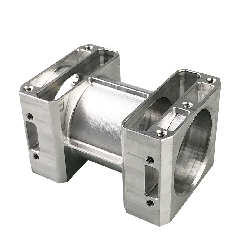
Before approaching BERGEK, the client had already been producing this 6061-T6 aluminum part with another CNC machining supplier. The part itself was not complicated—CNC turning, knurling, bead blasting, and silver anodizing.
Yet across multiple batches, they saw visible and repeatable inconsistency:
color shifts after anodizing (white / grey / slightly yellow)
different knurling depth and tactile feel
bead blasting roughness that changed batch to batch
chamfers appearing brighter due to uncontrolled geometry
overall sheen variation across the same production run
These problems were not one-time defects—they were systemic. So the client came to BERGEK with a clear request:
“We already know the part is manufacturable. What we need is every batch to look the same.”
Root Cause Analysis: Why Visual Drift Happens in CNC + Anodizing Workflows
After reviewing seven batches of parts provided by the client, we identified the underlying drivers of inconsistency. These were not isolated mistakes—they were cumulative process deviations.
1. Knurling depth inconsistency
The previous supplier had no tool-life control system. As knurling tools wore down, depth, sharpness, and tactile feel gradually drifted.
2. Unstable bead-blasting texture
Manual blasting caused differences in:
pressure
nozzle angle
distance
path
This directly affected anodizing appearance.
3. Fluctuating anodizing film thickness
Mixed loads (big + small parts) changed current density. Even a 0.5–1.0 μm film variance can shift color in silver anodizing.
4. Over-sharp chamfers
This is a design flaw, not an operator flaw. Sharp edges always reflect more light after anodizing.
The client immediately understood the real problem:
“This isn’t an anodizing issue. It’s the sum of small drifts at every step.”
Our Approach: Build a Repeatable CNC Machining System
Many CNC suppliers can produce one good batch. Few can produce five consecutive visually identical batches.
We focused on engineering a reproducible system, not just a nice sample.
1. Knurling tool-life curve + mandatory replacements
We created a wear-tracking curve and set pre-threshold replacement rules. Result: consistent depth and tactile feel, batch after batch.
2. Digitized bead-blasting parameters
We locked down:
blasting pressure
distance
angle
path using a fixture-guided route
This eliminated operator variability.
3. Anodizing current density based on surface area
No mixed loads. No uncontrolled film thickness variation. No grey shift.
4. Chamfer redesign for stable reflection
We adjusted the chamfer from 0.15 mm → 0.35 mm and applied controlled bead blasting coverage across the edge.
5. Batch traceability and data logging
Every key parameter is recorded and repeatable. Visual stability stops being an accident—it becomes engineered.
Engineering Intervention: Fixing the Chamfer Before Fixing the Color
The client’s original design included a nearly invisible chamfer. After reviewing their previous anodized parts, we explained:
“Sharp chamfers will always appear brighter after anodizing. It’s a physics issue, not an operator issue.”
Once the chamfer was redesigned and the bead-blasting coverage optimized, the visible bright-edge problem disappeared completely.
Final Results: Stable Across All Batches
After three verification rounds, production batches consistently achieved:
uniform knurling depth and tactile feel
stable natural-metal appearance after silver anodizing
no visible differences in sheen across batches
even bead-blasting texture without bright or dark spots
smooth chamfers without harsh reflection
“Bergek didn’t just fix the symptoms. They eliminated the way the problems kept happening.”
— Engineering Manager, European Smart-Device Manufacturer
Conclusion: CNC Machining Consistency Is a System, Not Luck
This case illustrates a truth often overlooked in CNC machining:
Appearance defects are rarely isolated.
They are system failures across the machining chain.
By controlling turning, knurling, blasting, anodizing, and inspection through a reproducible system, BERGEK delivered the stability the client had been unable to achieve elsewhere.
Stable batches are engineered—not hoped for.


